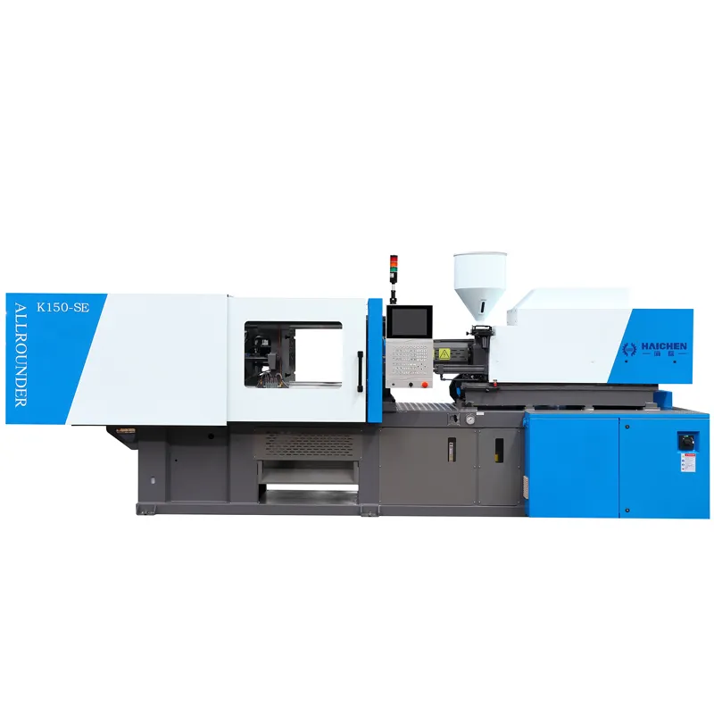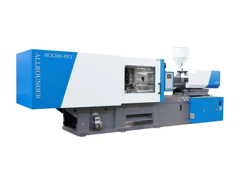
Surface quality is important in eyeglass frame injection molding. Black specks, silver streaks, flow marks, burn marks, weld lines, and warping can affect the appearance and fit of a frame.
These defects can come from several sources. Material condition, mold design, machine settings, and cooling all affect the final part. Therefore, changing one machine setting may not solve every problem.
In this guide, we explain how manufacturers can identify common surface defects, check the main causes, and improve the molding process.
We also share Haichen sunglass frame and temple configurations as real product examples.

What Causes Surface Defects in Eyeglass Frame Injection Molding?
Most surface defects fall into four main groups.
- Material: Moisture, contamination, poor storage, or material degradation can affect the surface.
- Mold: Gate design, venting, runner layout, and cavity condition can affect how plastic fills the mold.
- Machine: Plasticizing, injection control, and temperature control can affect melt quality and filling.
- Process: Injection speed, melt temperature, mold temperature, and cooling time can change the final result.
Start by checking when and where the defect appears. For example, a defect that appears in every cavity may have a different cause from one that appears in only one cavity.
This comparison can help narrow down the problem before changing several settings at once.
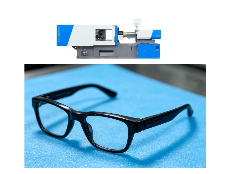
How to Prevent Black Specks and Silver Streaks
Black Specks
Black specks appear as small dark spots on the molded surface. They can come from contaminated material, degraded plastic, or material left in the screw, barrel, or other parts of the processing system.
To investigate black specks:
- Check the raw material for contamination.
- Review material storage and handling.
- Check whether the problem started after a material or color change.
- Review the processing temperature and residence time.
- Inspect the screw, barrel, and relevant flow paths if the problem continues.
Do not immediately increase or decrease the temperature without checking the material and machine condition. First identify whether the problem is related to contamination, degradation, or another source.
Silver Streaks
Silver streaks appear as shiny lines or streaks on the surface. Depending on the material and process, they may relate to moisture, gas, contamination, or material degradation.
For hygroscopic materials such as PET, proper drying is especially important. However, the required drying conditions depend on the specific grade and supplier recommendations.
A practical check includes:
- Confirming the material grade and its drying requirements.
- Checking the drying process and material storage.
- Inspecting the melt path for contamination or degradation.
- Reviewing injection conditions if the material checks do not explain the problem.
Do not assume that every silver streak comes from moisture. Compare the defect pattern and processing history before choosing a corrective action.
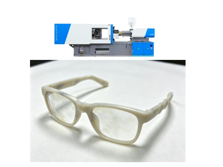
How to Reduce Flow Marks and Burn Marks
Flow Marks
Flow marks are visible lines or changes in appearance caused by differences in melt flow, temperature, or cooling. They may appear around changes in wall thickness, near the gate, or along the filling path.
Check the following points:
- Gate location: The gate should support a suitable filling pattern for the frame geometry.
- Injection conditions: Review injection speed and melt temperature according to the material and mold design.
- Wall thickness: Large changes in wall thickness can affect filling and cooling.
- Mold temperature: Uneven mold temperature may contribute to visible differences across the surface.
Change one process variable at a time and compare the results. If the marks remain in the same location, inspect the gate and mold design rather than relying only on machine adjustments.
Burn Marks
Burn marks are dark or discolored areas that may appear near the end of the filling path or in areas where air becomes trapped.
Possible causes include trapped air, poor mold venting, excessive local heating, or unsuitable injection conditions.
To investigate:
- Check whether the marks appear near the end of the filling path.
- Inspect the relevant mold vents.
- Check for blocked vents or contamination.
- Review injection speed and other process settings.
- Confirm whether the defect appears in one cavity or across several cavities.
If burn marks repeatedly appear in the same area, mold venting and the local filling pattern deserve attention. Simply lowering the temperature may not solve a problem caused by trapped air.

How to Reduce Weld Lines and Warping
Weld Lines
A weld line forms when two flow fronts meet but do not bond as well as the surrounding material. On an eyeglass frame, openings and other geometric features can split the flow and create meeting points.
Weld lines may become more visible because of the material, mold design, or processing conditions.
To investigate them:
- Check where the two flow fronts meet.
- Review the gate position and filling pattern.
- Inspect mold venting near the weld-line area.
- Review material-specific processing conditions.
- Check whether the line also affects the part’s strength or fit.
A weld line is not always removable through machine settings alone. If its position is determined by the mold layout, a mold-design change may be necessary.
Warping
Warping occurs when a molded part changes shape during cooling or after ejection. Uneven shrinkage and cooling can contribute to this problem.
Eyeglass frames and temples require attention to shape and fit. Even if a part looks acceptable immediately after ejection, it may change shape as it cools.
Check these factors:
- Cooling balance: Look for differences in cooling between areas of the mold.
- Wall thickness: Uneven sections may cool and shrink at different rates.
- Mold temperature: Check whether the temperature is consistent with the material and mold requirements.
- Holding conditions: Review holding pressure and time where appropriate.
- Ejection: Check whether the part deforms during ejection.
Measure the part after a consistent cooling period. This helps distinguish defects formed during filling from dimensional changes that develop after ejection.
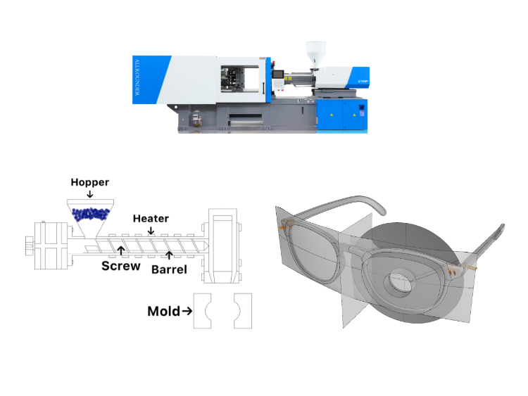
How the Injection Molding Machine and Mold Affect Surface Quality
A suitable machine must work well with the mold, material, and part requirements. Machine selection alone cannot guarantee a defect-free surface.
When reviewing a machine and mold combination, consider these points:
- Plasticizing: The screw and barrel must process the selected material under suitable conditions.
- Injection control: The machine must provide appropriate control over filling for the part and mold.
- Temperature control: Stable control helps maintain consistent processing conditions.
- Clamping and mold fit: The mold must fit the machine and close correctly.
- Cavity layout: More cavities increase the amount of material that must fill the mold in each cycle. The mold must also distribute the melt appropriately.
The Haichen examples include one-cavity and two-cavity frame molds, plus a four-cavity temple mold. Their product weights and cavity counts help define the mold’s filling requirements, but they are not enough to select a machine model or clamping force.
A proper selection also requires information such as the mold dimensions, projected area, material grade, complete shot requirement, and machine specifications.
How to Troubleshoot Surface Defects During Mold Trials
A structured trial process makes it easier to identify the cause of a defect. Avoid changing several machine settings at the same time because this makes the results harder to interpret.
Use the following steps:
- Record the defect. Take photos and note the location, appearance, and affected cavities.
- Check the material. Confirm the grade, storage condition, and any required drying.
- Inspect the mold. Check the gate, venting, cavity surface, and cooling system.
- Review the machine settings. Check the actual processing conditions against the material and mold requirements.
- Change one variable at a time. Record each change and compare the resulting parts.
- Check the finished part. Review its surface, dimensions, shape, and fit after a consistent cooling period.
- Document the result. Keep the successful settings and inspection results for future production.
If a defect remains, review the evidence before deciding whether the next step should involve the material, mold, or machine.
Some problems require mold modification or a material change rather than further adjustment of the machine settings.