Choosing the right injection molding machine starts with the right clamping force. If the machine cannot provide enough force, the mold may open slightly during injection.
As a result, the machine can produce flash, unstable dimensions, or other molding problems.
On the other hand, choosing a machine with far more clamping force than the application needs can increase equipment cost and mechanical load.
So, how do you calculate injection molding machine clamping force?
The basic formula is:
Required Clamping Force = Total Projected Area × Cavity Pressure × Safety Factor
The formula looks simple. However, you need the right data before you use it.
In this guide, we explain how to calculate clamping force step by step and how to use the result to select the right machine tonnage.
What Is Clamping Force?
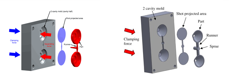
Clamping force is the force that an injection molding machine uses to keep the mold closed during the injection and packing stages.
When molten plastic enters the mold, pressure builds inside the cavities. This pressure pushes against the mold halves and tries to open the mold.
The clamping unit must provide enough force to resist this pressure.
Think of it this way:
Injection pressure tries to open the mold. Clamping force keeps the mold closed.
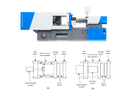
The machine generates clamping force through its clamping unit. Depending on the machine design, the clamping system may use a toggle mechanism, hydraulic system, or another mechanical structure.
For machine selection, however, the calculation principle remains similar: the machine needs enough rated clamping force for the mold and molding conditions.
Why Does Clamping Force Matter?
Correct clamping force helps the machine keep the mold stable throughout the injection process.
If the clamping force is too low, the mold can open at the parting line. This can cause:
- Flash
- Unstable part dimensions
- Material leakage at the parting line
- Higher scrap rates
- Mold and machine problems over time
However, more clamping force does not always mean better production.
Excessive force can place unnecessary load on the mold and clamping system. It can also increase equipment cost.
In some applications, excessive clamping force can make mold venting more difficult.
Therefore, the goal is simple:
Choose enough clamping force for stable production, but avoid unnecessary machine size.
What Information Do You Need?
Before you calculate injection molding machine clamping force, collect three key pieces of information:
- Projected area
- Plastic material
- Cavity number
You should also consider the runner system because the runner can contribute to the total projected area.
Projected Area
Projected area means the area that the molded part occupies when you look at it from the mold opening direction.
It is not the total surface area of the part.
A simple way to understand it is to imagine the part casting a shadow onto the mold parting line. That shadow represents the projected area.
For a rectangular part:
Projected Area = Length × Width
For a circular part:
Projected Area = π × Diameter² ÷ 4
For a multi-cavity mold, you need to calculate the projected area of all cavities.
You also need to consider the projected area of the runner system, especially when the mold uses a large cold runner.
Plastic Material
Plastic material affects the cavity pressure required during molding.
Different plastics have different flow characteristics. For example, a material with higher viscosity may need more pressure to fill a long or thin cavity.
However, material type alone does not determine cavity pressure.
You should also consider:
- Part wall thickness
- Flow length
- Gate location
- Melt temperature
- Mold temperature
- Injection speed
- Runner design
Therefore, do not use one pressure value for every plastic application.
For an early machine quotation, you can use a reasonable estimated pressure range. For a more detailed project, you can use material data, mold-flow analysis, or actual molding data.
That gives you a much more reliable result.

Cavity Number
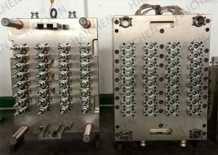
Cavity number directly affects the total projected area.
For example, suppose one cavity has a projected area of 50 cm².
A one-cavity mold has:
50 cm²
A four-cavity mold has:
50 × 4 = 200 cm²
An eight-cavity mold has:
50 × 8 = 400 cm²
So, even when each individual part is small, a high-cavity mold can require much more clamping force.
That is why you should always calculate the total projected area instead of looking at one cavity only.
How to Calculate Clamping Force
Once you have the required information, you can calculate the clamping force.
The basic formula is:
Basic Clamping Force = Total Projected Area × Cavity Pressure
Then add a safety factor:
Required Clamping Force = Total Projected Area × Cavity Pressure × Safety Factor
When you use cm² and kgf/cm², you can convert the result into tons with this formula:
Required Clamping Force (tons) = Total Projected Area (cm²) × Cavity Pressure (kgf/cm²) ÷ 1,000 × Safety Factor
The unit conversion matters. You can also work with MPa, kN, or other units, but you must keep the units consistent throughout the calculation.
Calculate Projected Area
First, calculate the projected area of one cavity.
For example:
- Part length = 100 mm
- Part width = 80 mm
Convert the dimensions to centimeters:
- Length = 10 cm
- Width = 8 cm
Then:
Projected Area = 10 × 8 = 80 cm²
Now suppose the mold has four cavities:
Part Projected Area = 80 × 4 = 320 cm²
If the runner adds another 30 cm²:
Total Projected Area = 320 + 30 = 350 cm²
Now you have the main area required for the clamping force calculation.
Remember, the projected area comes from the mold opening direction. Do not use the total surface area of the product.
Choose Mold Pressure
Next, you need an estimated cavity pressure.
This step requires more engineering judgment than the area calculation.
Do not simply use the maximum injection pressure listed in the machine specification.
Machine injection pressure and cavity pressure are different.
Machine injection pressure refers to the pressure generated by the injection unit. Cavity pressure refers to the pressure that develops inside the mold cavity during filling and packing.
Pressure changes as the plastic flows through the nozzle, runner, gate, and cavity.
Therefore, cavity pressure depends on the complete molding process.
For a preliminary calculation, you can estimate the pressure based on:
- Plastic material
- Part geometry
- Wall thickness
- Flow length
- Gate design
- Runner design
- Processing temperature
- Injection speed
For a production project, mold-flow analysis can provide a more accurate estimate.
As a machine manufacturer, we also recommend checking the actual mold and material conditions before confirming the final machine size.
Add a Safety Factor
After calculating the basic clamping force, add a safety factor.
A common preliminary range is around 1.10 to 1.20.
For example, if the basic calculation gives 180 tons and you use a 1.15 safety factor:
180 × 1.15 = 207 tons
The estimated requirement becomes about 207 tons.
You would then evaluate the available standard machine sizes and normally move to the next suitable machine size.
The safety factor should provide a reasonable operating margin. It should not become a reason to choose an unnecessarily large machine.
How to Choose Machine Tonnage
The calculated clamping force does not always match a standard machine size.
For example, your calculation may give 207 tons, while the manufacturer offers 200T and 230T machines.
In this case, you need to compare the calculated requirement with the available machine specifications.
Compare Required Force With Machine Tonnage
Suppose the calculated requirement is:
Required clamping force = 207 tons
A 200T machine does not reach the calculated requirement.
A 230T machine provides a higher rated clamping force and becomes the next machine size to evaluate.
However, you should not make the final decision from tonnage alone.
You should also confirm that the machine can work with the mold and production requirements.
For example, check:
- Mold size
- Tie-bar spacing
- Platen dimensions
- Mold thickness
- Mold opening requirements
- Ejector requirements
- Injection unit requirements
The clamping unit and injection unit must work together as one complete system.
So, the calculated tonnage gives you the starting point. The complete machine specification gives you the final answer.
Avoid Too Little or Too Much Clamping Force
Too little clamping force can allow the mold to open during injection.
For example, if the application requires about 210 tons but you select a 160T machine, the machine may not keep the mold closed under the required cavity pressure.
This can lead to flash and unstable production.
However, choosing a much larger machine also creates unnecessary cost.
For example, if the application needs about 210 tons, moving directly to a 400T machine does not automatically improve product quality.
A much larger machine can cost more and occupy more floor space. It may also create unnecessary mechanical and energy costs.
Therefore, choose a machine that provides enough clamping force with a reasonable operating margin.
In short:Too little force creates production risk. Too much force creates unnecessary cost.